Synchronous Logic
In a combinational circuit, the outputs are not instantenously updated to their correct values when an input changes (or when the circuit is powered on), since each gate and interconnect has a propagation delay.
For a combinational circuit, this means we have to wait for a certain amount of time after changing the inputs, before considering the outputs to be valid.
For sequential circuits, however,
the propagation delay represents a challenge.
The outputs are not only a function of the inputs,
but also of the previous inputs.
We need to pay attention to the order of events,
to ensure state elements and outputs are properly updated.
Often, we want simultaneous updates to distinct state elements:
e.g. a two-bit counter incremented from 01 to 10 without being
interpreted as 00 or 11 in the process,
just because one of the bits happens to be flipped slightly before the other.
The synchronous logic is a solution to this problem,
in which every state update is controlled by
a single synchronizing clock signal,
which is usually a periodic square wave
alternating between 0 and 1 with a certain frequency,
i.e. the clock rate.
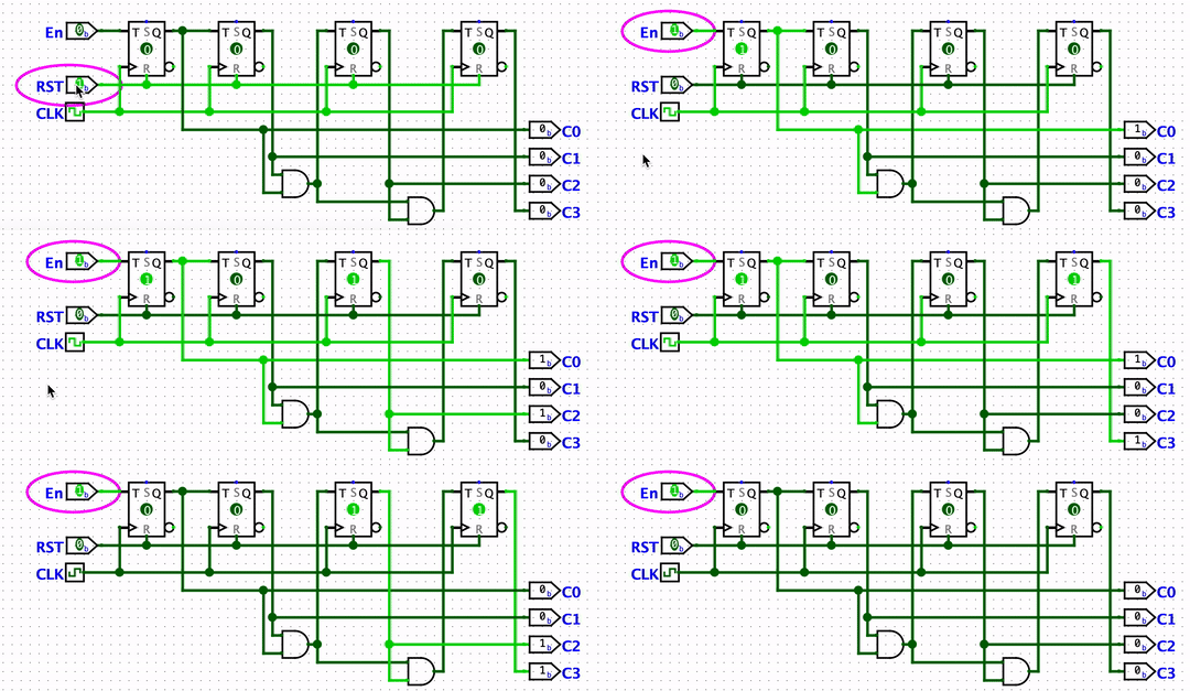
The logic shown below is a four-bit counter, implemented using T flip-flops.

The counter value is cleared when RST (reset) is 1.
If En is 1 (enabled), it will count up every time
the CLK (clock) signal switches from 0 to 1.
This transition is called the “positive edge”
or the “rising edge” of the clock.
The small triangle in the T flip-flops indicate
that updates are “triggered” by this rising edge.
Note that all the state is connected to one single clock signal for synchronization. This makes it easier to design and study circuits.
You can open the sync.circ file in Logisim to examine this circuit.