Propagation Delay and Clock Period
Propagation Delay
Logisim does not properly model propagation delays,
but it simulates the operation of circuits in iterations,
We can visualize these iterations
using the Simulate -> Single-Step Propagation menu option,
and see the order of events
as changes propagate through gates and interconnects.
The five-bit counter below is similar to the previous circuit, except this one is implemented with D flip-flops.
Starting with the counter value 11110
(read the flip-flops bottom to top),
the rising clock edge causes
flip-flop contents to be simultaneously
updated—only the topmost flip-flop changes in this case.
After a certain delay (called CLK-to-Q delay),
the updated values appear on the Q output of the flip-flops,
representing the counter value 11111.
Sent through the combinational gates,
these bits are used to determine the next value of the counter,
which is 00000.
At the next rising clock edge,
all flip-flops will be changed to 0.
You can find this circuit in the Logisim file called propagation.circ.
Clock Period
As can be seen in the above example,
the input to the bottom flip-flop is the latest
to be calculated,
as the signal passes through four AND gates,
and one XOR gate.
This path has the largest propagation delay,
i.e. this is the critical path.
Only after every flip-flop input is valid and ready, we can start the next update to flip-flop contents. For correct operation, the next rising clock edge should not happen before the signals are propagated, stabilized, AND are held stable for a period of time—called setup time—required for updating the flip-flops.
These requirements are the determining factors for the minimum amount of time between successive rising clock edges, i.e. the minimum clock period:
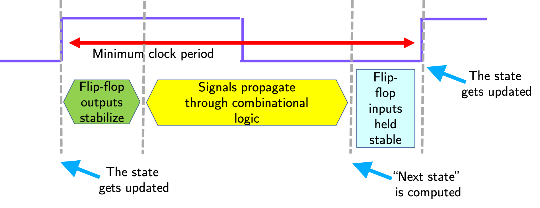
Since the clock rate, or clock frequency, is the inverse of the clock period, this also determines the maximum clock frequency.